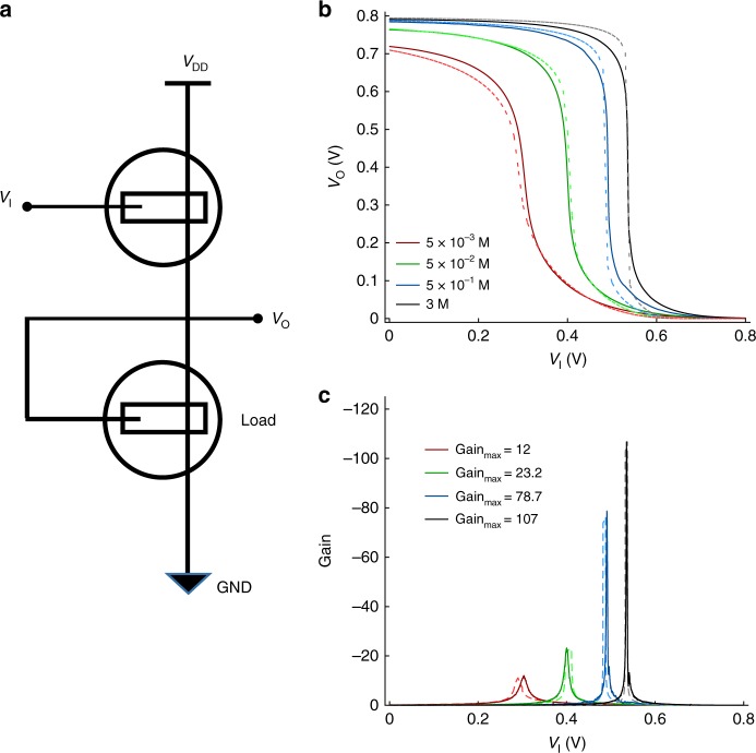
Fig. 8.
Unipolar OECT based inverter. a Schematic of the designed circuit. The driver geometries are W = 1000 µm, L = 500 µm, t = 210 nm, the load geometries are W = 1000 µm, L = 500 µm, t = 280 nm. Crys-P is used for the OECT channel, and details are provided in Supplementary Note 4. b Measured (solid line) and simulated (dashed lines) voltage transfer characteristics of the inverter. c Measured (solid line) and simulated (dashed lines) gain of the inverter

