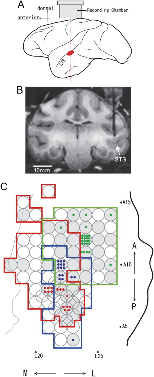
Figure 2.

Recording sites. A, Schematic illustration showing the recording site within a lateral view of the monkey cerebral cortex (in red) and the approximate position of the recording chamber. B, An MRI image of a coronal section of the brain of monkey AQ positioned 8 mm anterior to the interaural line. A guide tube made of gold 650 μm in diameter is inserted targeting the lower bank of the STS in the right hemisphere. C, Top view of the areas of electrode penetration in the lower bank of the STS in three hemispheres are indicated by colored contours (red, monkey AQ right hemisphere; blue, AQ left; green, TV left) with stereotaxic coordinates. A thick black line indicates the lip of the STS, and a thin gray line indicates the fundus of the STS in one hemisphere (AQ right). The positions of the lip and fundus of the STS in the other two hemispheres were very similar to those shown here. The circles indicate the positions of grid holes where electrodes were penetrated, and the gray circles indicate the positions where neurons responsive to the gloss stimulus set were obtained. A colored dot indicates the position where a gloss-selective neuron was recorded.
