
Figure 5.
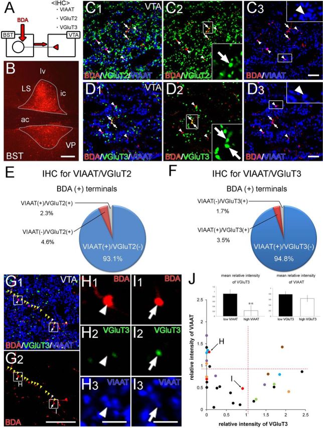
Combined anterograde tracer labeling and immunofluorescence showing neurochemical composition of nerve terminals projecting from the BST to the VTA. A, Experimental diagram. B, Injection site of BDA in the BST. C, D, Triple immunofluorescence for VGluT2 (green in C) or VGluT3 (green in D) together with VIAAT (blue) and BDA (red) in the VTA. Most BDA-labeled terminals are VIAAT+ (arrowheads in C, D) with a few VGluT2+ (arrows in C) or VGluT3+ (arrows in D) terminals. E, F, Neurochemical composition of VTA-projecting BST neuron terminals as determined from triple immunofluorescence for VGluT2/BDA/VIAAT (E) and VGluT3/BDA/VIAAT (F). G–I, VGluT3 and VIAAT immunofluorescence in terminals on a single BDA-labeled BST axon in the VTA (yellow arrowheads). The two terminals indicated by the arrowhead and arrow in G are enlarged in H and I, respectively, to show that a single BDA-labeled axon can produce VIAAT+/VGluT3− (H) and VIAAT+/VGluT3+ (I) terminal boutons. J, Plot showing relative intensity for VGluT3 and VIAAT in individual terminals on BDA-labeled BST axons in the VTA. Dots in the same color represents boutons derived from the same axons. Red dashed lines represent the threshold value to divide into high- and low-intensity groups. Insets show the comparison of relative fluorescence intensities for VGluT3 between low and high VIAAT groups (left) and for VIAAT between low and high VGluT3 groups (right). Error bars represent the SEM. **p < 0.01 (Mann–Whitney U test). IHC, Immunohistochemistry. For other abbreviations, see Figure 2. Scale bars: B, 200 μm; C, D, 10 μm; G, 30 μm; H, I, 5 μm.