Figure 6.
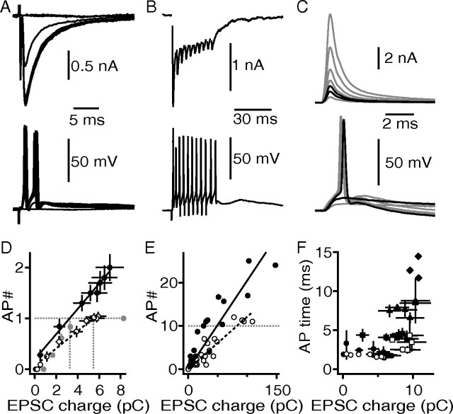
The NMDAR currents enhance the synaptically IO-F. A, Synaptically evoked EPSCs recorded at −60 mV (top), and synaptic evoked voltage response of the same neuron in current clamp (bottom). For both recording modes, the stimulus intensity was varied between 80 and 0 V, applied to the same stimulation site. B, Synaptically evoked EPSCs from a 10 pulse, 333 Hz stimulus train (top). The same stimulus was applied in current clamp (bottom). The cell is the same as in A. C, Injection of a simulated and scaled EPSC (simEPSC) waveform as a current-clamp command (top). Bottom shows the corresponding evoked voltage response to the simEPSC. The black traces in the top and the bottom graph depict the subthreshold and suprathreshold current injections. D, Synaptic IO-Fs of cells from experiments in A and C. The solid circles represent data from the control population (n = 16), open circles represent data from cells recorded with bath-applied d-AP5 (n = 19), and the gray circles represent data obtained with simEPSC current injections (n = 5). The black solid and dotted lines represent linear regression fits. The gray dotted lines indicate the amount of EPSC charge needed to trigger one AP. E, Same graph as in D, additionally including data from experiments in B. Regressions were fit with a fixed zero x–y crossing. F, Occurrence of AP in time in response to a single afferent fiber stimulation event plotted as a function of EPSC charge. The circles represent first; squares, second; triangles, third; and diamonds, fourth evoked AP. The solid symbols show control data, and the open symbols show cells recorded in the presence of d-AP5.

