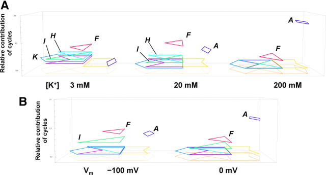
Figure 6.
The visualized permeation processes. A, The relative contributions of the cycles at different K+ concentrations. The eight state diagram is shown as the footprint, above which the cyclic paths predominantly used in the permeation are demonstrated (the dark blue diamond for cycle A, the red triangle for cycle F, the light blue triangle for cycle H, the green triangle for cycle I, and the blue escutcheon for cycle K). The relative contributions of cycles are expressed as the level of height raised from the footprint. Cycles contributing to the net flux <0.01 are not shown. At 200 mm, the relative contribution of cycle A was 0.83, and that of cycle F was 0.15; at 20 mm, that of cycle A was 0.29, cycle F was 0.42, cycle G was 0.03, and cycles H and I were 0.11; and at 3 mm, that of cycle A was 0.04, cycle F was 0.34, cycle G was 0.09, cycles H and I were 0.18, cycle K was 0.13, and cycle L was 0.03. B, Predicted relative contributions of cycles at different membrane potentials in an asymmetric condition of 4 mm Kout and 150 mm Kin. At 0 mV, the relative contribution of cycle A was 0.62, cycle F was 0.22, cycle H was 0.01, cycle I was 0.11, and cycle L was 0.02; at −100 mV, that of cycle A was 0.34, cycle F was 0.38, cycle G was 0.02, cycle H was 0.03, cycle I was 0.22, and cycle L was 0.02.

