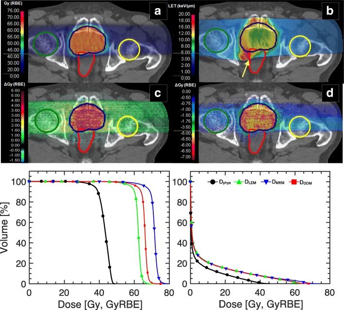
Fig. 3.
DRBE comparison illustrated in a clinical case (prostate cancer). a MC-optimized DRBE distribution applying the DDM for the prostate case with resulting (b) LETd distribution for Z = 2 particles. c Differences between the reference DRBE (DDM) and LEM and MKM DRBE are displayed in panels (c) and (d), respectively. Contours for the PTV, femurs and rectum are displayed in blue, green/yellow and red, respectively. DVH and DRBEVH for the three biological models are depicted for the PTV and the rectum in the bottom left and right panel, respectively. Note that the critical organs at risk (e.g. anterior rectum) are susceptible to large variations in small volumes (< 5% of the relative total volume per organ) due to overlap with the tumor structure delineation. The asymmetric LETd gradient (indicated by the yellow arrow) in panel (b) is indicative of the applied beam optimization procedure to meet dose constraints in the rectum while maintaining target coverage

