-
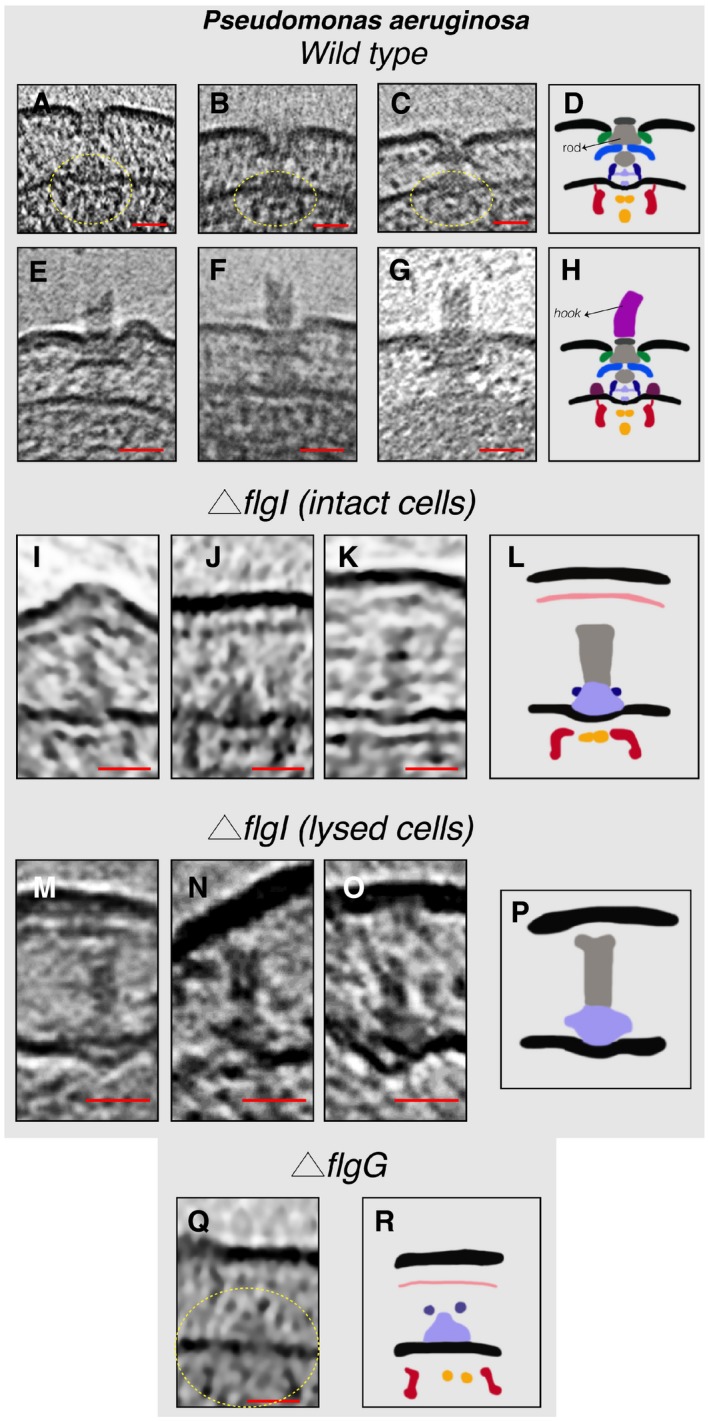
A–C
Slices through electron cryo‐tomograms showing fully assembled motors without the hook and filament. The dashed yellow circles indicate the IM sub‐complex.
-
D
Schematic representation of the P. aeruginosa motors lacking the hook and filament shown in (A–C).
-
E–G
Slices through electron cryo‐tomograms showing fully assembled motors with the hook and lacking the filament.
-
H
Schematic representation of the motors with the hook shown in (E–G).
-
I–K
Slices through electron cryo‐tomograms of intact P. aeruginosa ΔflgI cells showing the presence of the inner‐membrane sub‐complex with the rod.
-
L
Schematic representation of the inner‐membrane sub‐complex with the rod shown in (I‐K).
-
M–O
Slices through electron cryo‐tomograms of lysed P. aeruginosa ΔflgI cells showing the presence of the sub‐complex constituting the MS‐ring and the rod.
-
P
Schematic representation of the sub‐complex described in (M–O).
-
Q
A slice through an electron cryo‐tomogram of a P. aeruginosa ΔflgG cell highlighting the presence of the inner‐membrane sub‐complex.
-
R
Schematic representation of the inner‐membrane sub‐complex shown in (Q).
Data information: All scale bars 25 nm.

