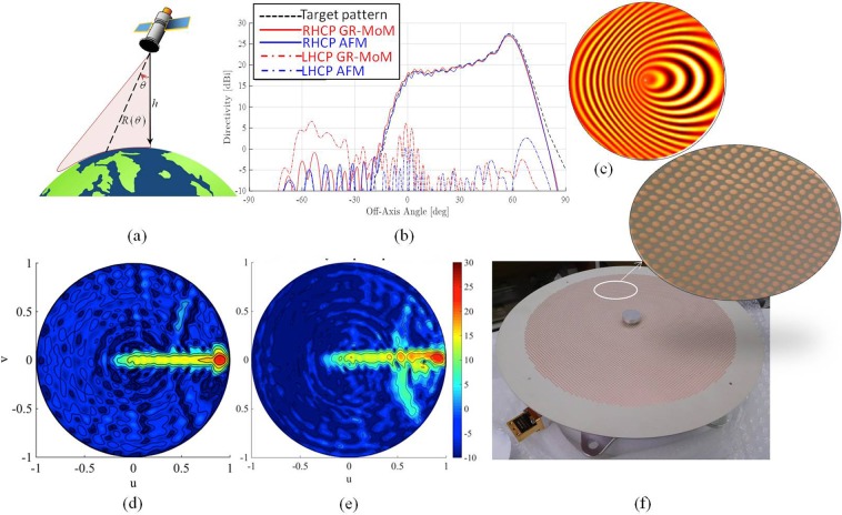
Figure 4.
Operative environment, layout and performances of the shaped beam MTS antenna; (a) sketch of the Earth surface coverage obtained by using a sectorial isoflux antenna with a turn-table mechanism; (b) simulated directivity pattern of a sectorial isoflux MTS antenna for Earth observation missions from LEO satellites; (c) sketch of the impedance pattern on the metasurface; (d) simulated RHCP component of the directivity for the isoflux sectorial beam antenna in the u-v plane; (e) measured RHCP component of directivity for the isoflux sectorial beam antenna in the u-v spectral plane at 26.4 GHz; (f) picture of isoflux sectorial beam antenna realization with a detail of the pixelated surface. In the center of the aperture, a metallic cap allows one to improve the antenna matching and the SW launching efficiency.

