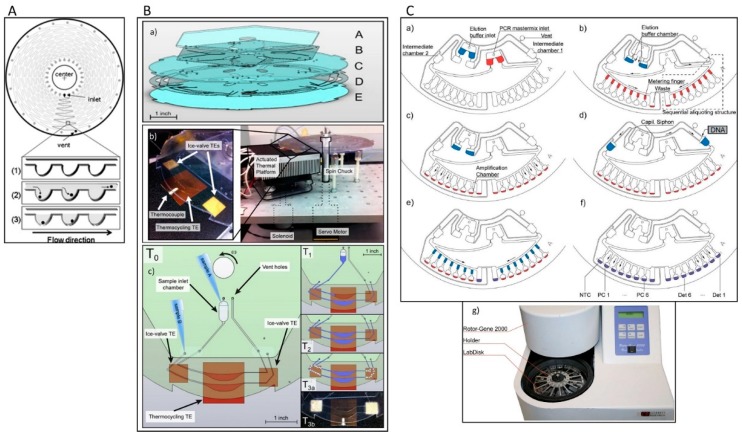
Figure 3.
(A) Microfluidic design of a compact disc (CD) device and schematic illustration of single cell isolation: (1) a large number of microchambers align along a channel, (2) the cells flow through the microchambers and (3) are spread into individual microchambers [69]. (B) (a) Schematic graph of the multi-layered centrifugal disc. The disc is comprised of five layers of hard plastic: A. polycarbonate sheet, B. pressure sensitive adhesive tape (PSA), C. polycarbonate sheet, D. polycarbonate film, and E. polycarbonate film. (b) (Right) Image of the integrated centrifugal microfluidic platform for pumping, valving, and thermocycling of fluid. (Left) Close-up of the actuated thermal platform showing the location of the central thermocycling TE and two ice-valve TEs. (c) Schematic presentation of the hardware details and fluidic process for the integrated CD system [70]. (C) Schematic illustration of one microfluidic structure: (a) elution buffer and PCR mastermix are loaded to the inlets, (b) the elution buffer is transported into two elution buffer chambers while the PCR mastermix is distributed into metering fingers, (c) the PCR mastermix aliquots are gated into amplification chambers which filled with primers, (d) DNA is added to one of the sub-volumes, (e) each subvolume is aliquoted into several aliquots, (f) PCR is started, and (g) the Lab Disk is mounted to a custom-made holder [71]. Reproduced from the mentioned references with permission from the related journals.

