
Figure 31.
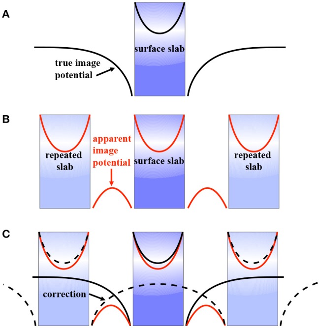
The image potential of a repeated slab system (B) differs from that of an isolated surface (A). The dashed lines in (C) mark the difference that can be computed with a suitable correction scheme (Freysoldt et al., 2008). As the charge moves across the interface, the ratio of dielectric constants for the “charged” and “uncharged” regions changes. As a result, the image potential changes sign.