. 2019 Jul 8;8:e46515. doi: 10.7554/eLife.46515

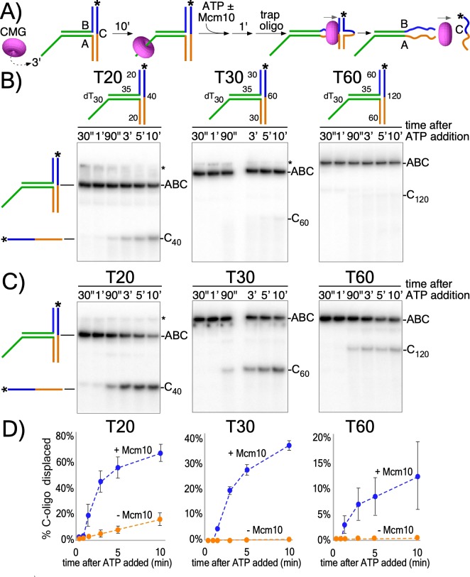
Figure 2. CMG translocates with force while encircling duplex DNA.

(A) Schematic of reactions using T-substrates with a 3’ dT30 ssDNA tail for CMG loading, a flush ss/ds junction and 35 bp of dsDNA (green) preceding the non-homologous arm blocks (blue and orange). See Figure 2—figure supplement 1 for details on the substrates. Unwinding the 32P-cross-bar oligo (labeled with a *) requires CMG to track with force while encircling dsDNA. (B) Native PAGE gel of time course reactions using CMG (no Mcm10) on T-substrates with different length arms. (C) Repeat of (B) with addition of Mcm10. (D) Plots of the data from (B) and (C). Values shown are the average of three independent experiments and the error bars show one standard deviation. The asterisks to the right of the gels indicate gel-shift of the substrate by CMG and Mcm10. See also Figure 2—figure supplements 23.

Figure 2.

Figure 2—figure supplement 1. The T-shaped substrates shown in schematic form.
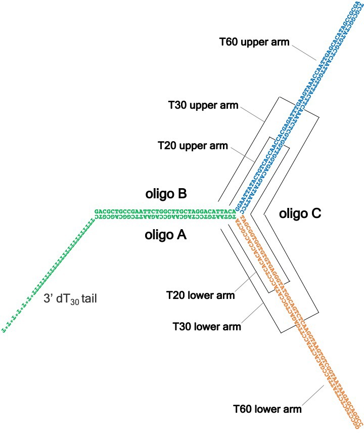
Figure 2—figure supplement 1.

These substrates, used in Figure 2 to demonstrate duplex DNA translocation with force by CMG ± Mcm10, consist of three partially complementary oligonucleotides, denoted as A, B and C. Oligo A contains a 3’ dT30 tail required for CMG loading (Figure 2—figure supplement 2) and Oligo B forms a flush duplex with oligo A (green) to allow CMG to thread onto dsDNA without unwinding it. The duplex formed by oligos A and B is followed by two regions of non-complementarity (shown in blue and orange) that vary in length depending on the substrate, as indicated. These non-complementary arms are bound by a third oligo, C, which is complementary to the upper B arm (blue) and the lower A arm (orange). Active duplex translocation by CMG ± Mcm10 is required to dislodge the C oligo by breaking the base pairs in the upper and lower arms. Oligo C is radiolabeled in the experiments of Figure 2 and complete unwinding of oligo C is monitored by its altered migration in a native PAGE gel. See Supplementary file 1 for sequences of the oligos used to construct the T20, T30 and T60 substrates.

Figure 2—figure supplement 2. The 3’ dT30 tail is required for CMG loading onto the T-substrates.
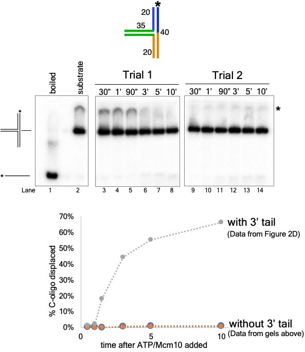
Figure 2—figure supplement 2.

The experiment from Figure 2C (CMG+Mcm10) was repeated using a T20 substrate with no 3’ dT30 loading tail by substituting oligo “T20A no 3’ tail” (see Supplementary file 1 for sequence) for oligo T20A. A schematic of the substrate is shown (top) as are gels from two separate trials of the experiment using this substrate (middle). The graph below shows a comparison of unwinding using the substrate with no 3’ tail to that of the 3’-tailed T20 substrate (data from Figure 2C, (D). The * next to the gels indicates gel-shift of the substrate by CMG+Mcm10.

Figure 2—figure supplement 3. Mcm10 does not unwind the T-substrates without CMG.
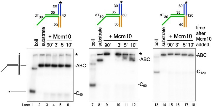
Figure 2—figure supplement 3.

The experiments of Figure 2C were repeated using Mcm10 (no CMG) with the T20 substrate (lanes 3-6), the T30 substrate (lanes 9-12) and the T60 substrate (lanes 15-18). The unreacted substrate is shown in lanes 2, 8, and 14 and lanes 1, 7, and 13 show the migration of the unwound product by boiling. The * next to the gels indicates gel-shift of the substrates by Mcm10.