Fig. 3.
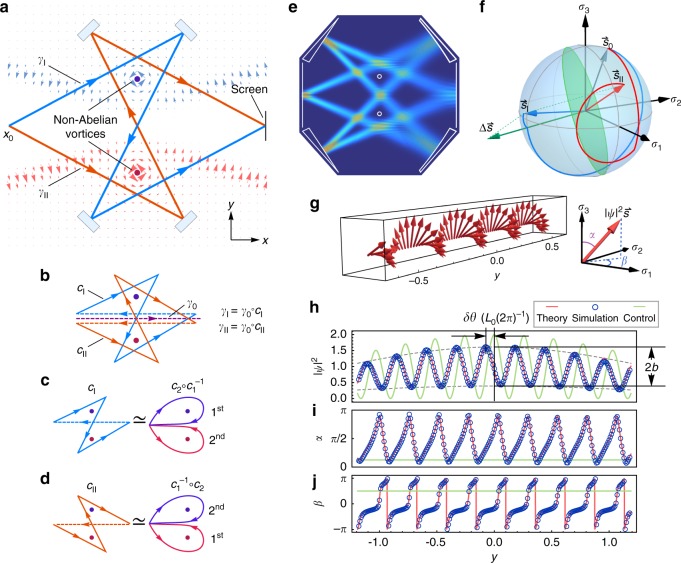
Genuine non-Abelian AB effect for light. a Sketch of the non-Abelian AB system with two optical paths , interfering on the screen, where the background light blue (red) arrows denote the () component of the non-Abelian vector potential. b () can be divided into a closed loop () and a common path γ0. c, d cI and cII can, respectively, deform continuously into a closed path that winds around the two vortices successively but in opposite sequences. e Snapshot of the simulated field intensity for the proposed non-Abelian optical interferometer with incident spinor for both beams and the vortex fluxes , . f Spin evolution on the Bloch sphere along two beams , , which share the same initial spin but achieve different final spins and . g Spin density interference corresponding to e, where each arrow denotes the local pseudo-spin density at a point on the screen. All of the local spins are perpendicular to , and thus fall on the green circle in f. The corresponding intensity interference and the two Euler angles α, β of the local spins on the screen are shown in h–j, where blue circles and red curves indicate simulated and theoretical results, respectively, and , b are the phase shift and relative amplitude relative to the case of (L0 is the period of ). The green lines correspond to the “control experiment”

