Fig. 1.
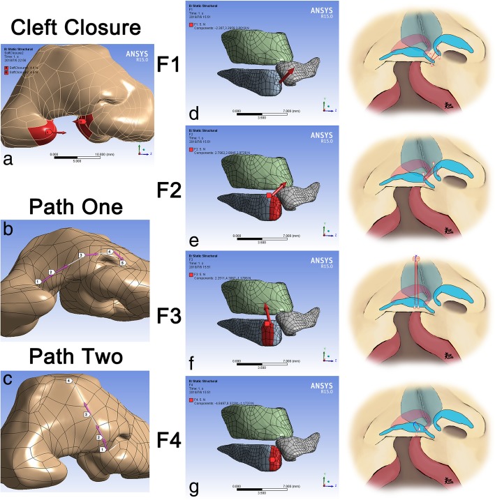
Vectors of force loadings and definition of paths. a Two opposite forces at both sides of the cleft to simulate the closure of cleft lip; b Path one was defined by the alar bases at both sides (Landmarks one, five), the alar domes at both sides (Landmark two, four) and the nasal tip (Landmark three); c Path two was defined by the columella base (Landmark one), the nasal tip (Landmark two), the dorsum (Landmark three) and the nasal radix (Landmark four); d Medially, anteriorly and cranially directed force on the tip of medial crus (F1) to simulate the suture fastened both medial crura together; e Medially, posteriorly and cranially directed force on the medial crus (F2) to simulate the suture sewing both medial crura and the non-cleft-side upper lateral cartilage together; f Force directed to the nasal radix and paralleled to the dorsum on the intermediate crus (F3) to simulate the suture elevating the alar cartilage cranially; g Anteriorly directed force on the intermediate crus (F4) to simulate the suture elevating the alar cartilage superiorly. (b, c, d, e Right) Surgical maneuvers illustration for each force. Red line, suture inside the body. Blue line, extracorporeal suture

