
Figure 5.
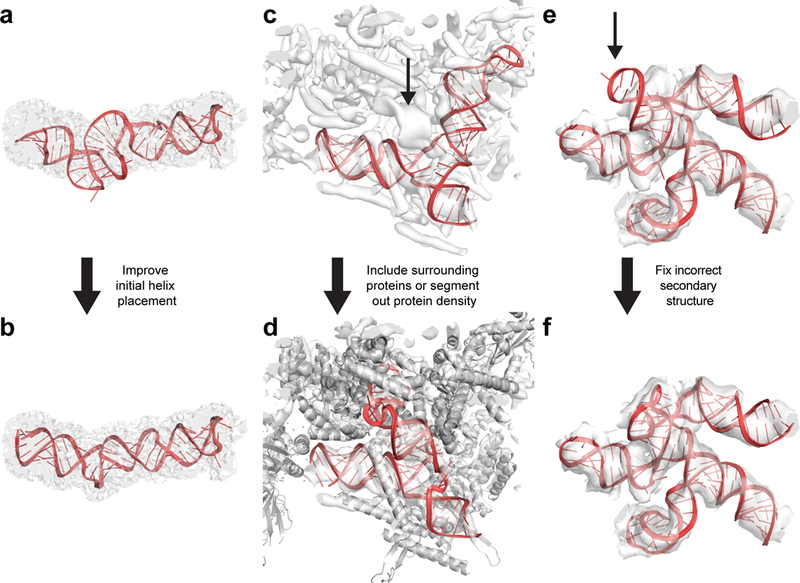
Typical mistakes that may occur during DRRAFTER modeling and possible solutions. (a) Poor initial helix placement can lead to distorted final models, as shown here for residues 153–227 of the packaged MS2 genome (RNA colored red, density map colored transparent gray). (b) This can be fixed either by improving the initial helix placement, or by skipping the helix placement step and letting DRRAFTER determine the helix placement de novo. Here, this improved model was built by omitting the initial helix placements. (c) When proteins are not included during DRRAFTER modeling, RNA models may be built into protein density as shown here for the spliceosomal tri-snRNP U4/U6 three-way junction (RNA colored red). The actual density for the RNA is indicated with the black arrow. (d) This can be fixed either by including the surrounding proteins during the DRRAFTER modeling, as shown here (proteins colored gray), or by segmenting the protein density out of the map before modeling. (e) Visual inspection can identify models that do not fit well in the density map, as shown here for SL3–4 of the yeast spliceosomal U1 snRNP (black arrow). This can be caused by inadequate sampling, in which case building more models and/or increasing the number of cycles used to build each model should solve this problem. Alternatively, some of the modeling assumptions, such as the RNA secondary structure, or fixed positions of surrounding RNA or protein residues may be incorrect. (f) In this case, the secondary structure assumed as part of the initial modeling was incorrect. When the secondary structure was corrected, we were able to build DRRAFTER models that fit in the density map.