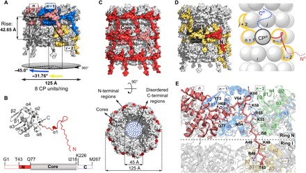
Fig. 3. Structural features of VLP.

(A) Surface representation of two rings in a VLP filament with colored units CPn (pink), CPn−1 (blue), and CPi−2 (yellow). (B) Structure of VLP CP (N-terminal region, red; core, gray). Bottom: A linear representation of the CP, using the same colors as in the model above. Dashed boxes at N- and C-terminal regions depict structurally disordered parts. (C) Side and top views of the VLP filament; the colors are as in (B). Position of one CP unit (pink) is shown in the filament. (D) Protein-protein interactions in the VLP filament. Surface (left) and schematic (right) representation of central CPn unit (N-terminal region, red; core, dark gray; C-terminal region, blue) interacting with four neighboring CP units (yellow). N- and C-terminal regions in the scheme are shown only for the unit CPn. The dotted lines in N- and C-terminal regions indicate disordered parts. (E) Interface between the N-terminal region of the CPn unit (pink) and neighboring units CPn−1 (blue) and CPi−2 (yellow). CPn−2 (no interactions with CPn) is shown in green.
