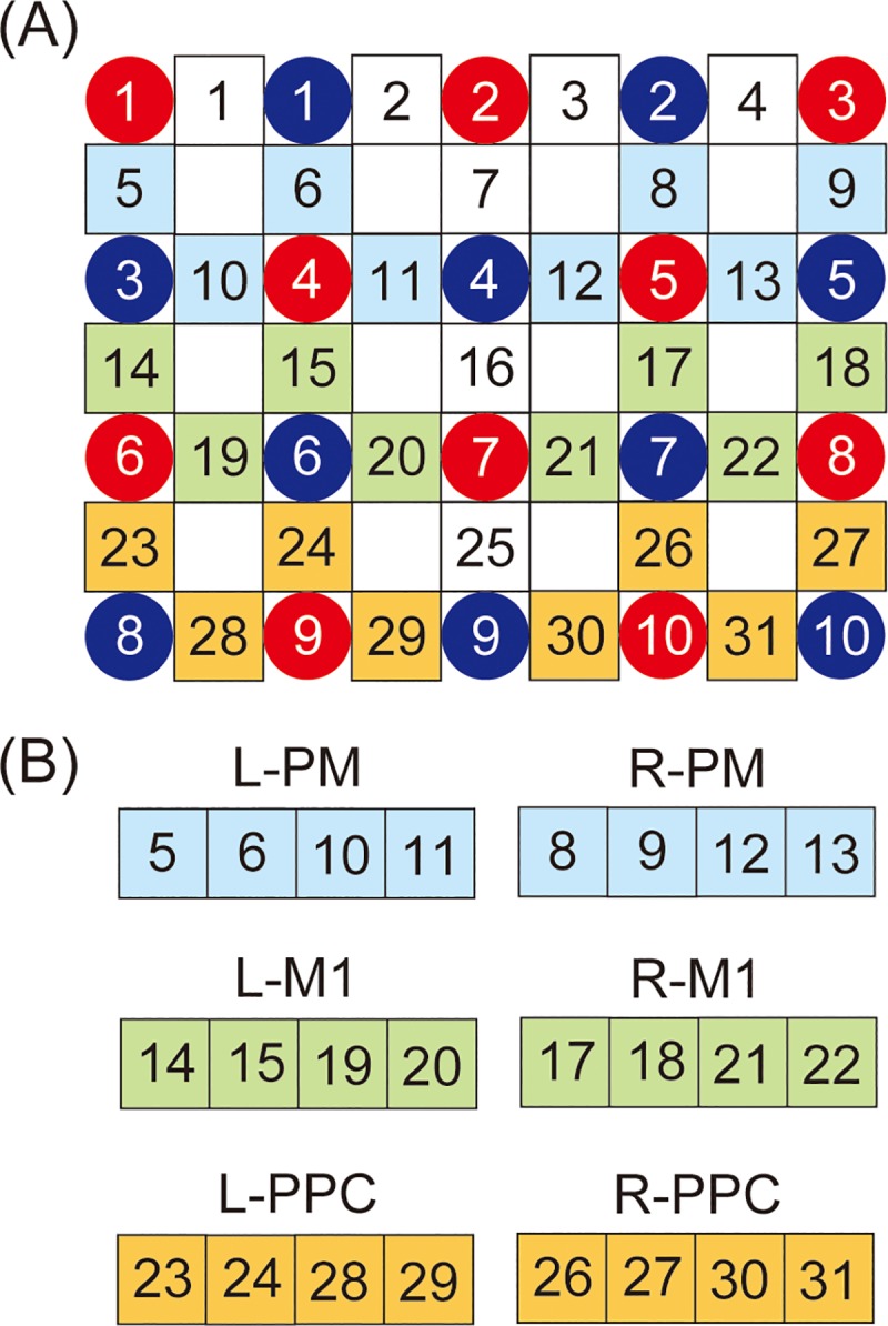
Fig 3.

(A) Channel configuration of the optical probes. Ten red and blue circles indicate the positions of NIRS sensors and detectors, respectively, in 31 optical channels (5 x 4 optical probe set). (B) The defined regions of interest (ROIs). L-PM = left premotor cortex; R-PM = right premotor cortex; L-M1 = left primary motor cortex; R-M1 = right primary motor cortex; L-PPC = left posterior parietal cortex; R-PPC = right posterior parietal cortex.
