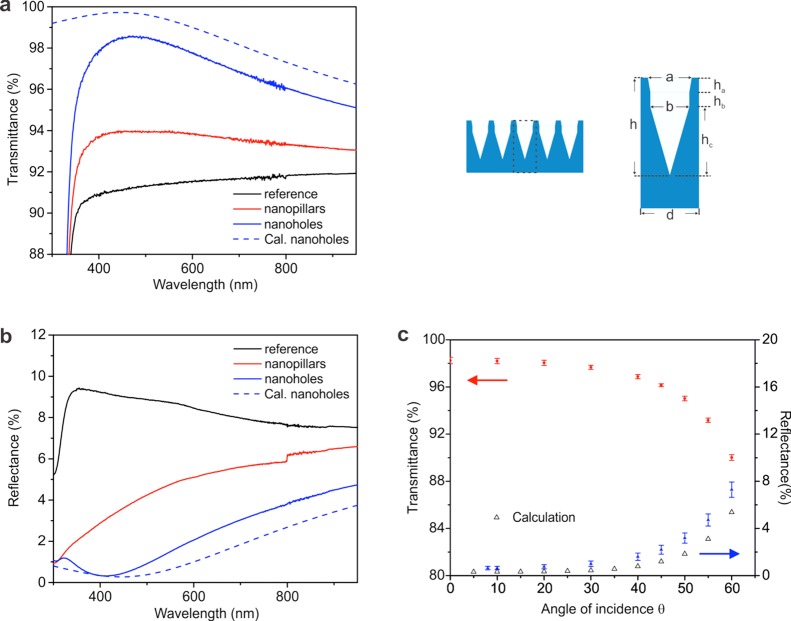
Figure 3.
Transmittance and reflectance of a borosilicate glass substrate with nanoholes or nanopillars on both sides. (a,b) Comparison of the transmittance and reflectance (300–950 nm) of a borosilicate glass substrate with 200 nm nanoholes on both sides (in blue), a borosilicate glass substrate with 120 nm nanopillars on both sides (in red), and the reference sample without nanostructures (in black). The calculated transmittance and reflectance of the substrate with 200 nm nanoholes are in dashed red and blue curves. Parameters of nanoholes in calculation: h = 200 nm, d = 105 nm, a = 90 nm, b = 80 nm, ha = hb = 30 nm, and hc = 140 nm. (c) Measured average (380–500 nm) transmittance (red circles), reflectance (blue triangles), and calculated reflectance (black triangles) of the borosilicate glass substrates with 200 nm nanoholes on both sides shown in (a,b) measured at different angles of incidence.

