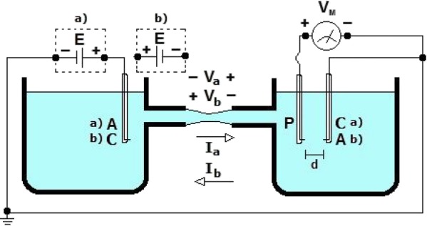
Figure 1.

Schematic diagram of the circuit used to measure the space-charge region at the cathode indicated by circuit (a) and at the anode indicated by (b). Two power supplies were used: in configuration (a), the cathode is grounded, and in configuration (b), the anode is grounded.
