
Fig. 1.
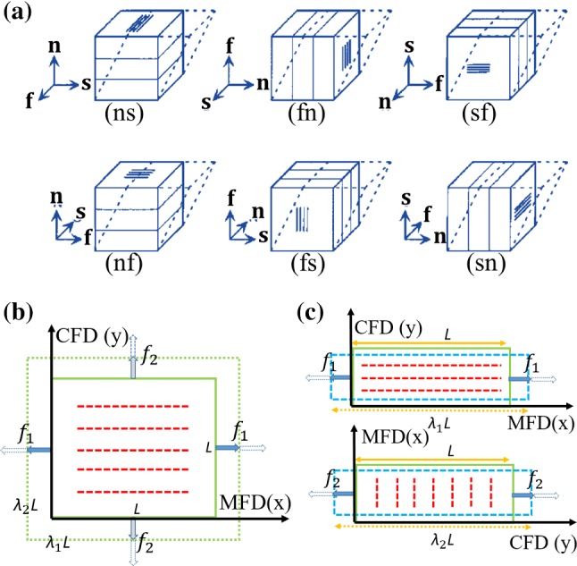
a A sketch of all six possible shear modes, , , and denote the fibre, sheet, and normal direction, respectively. (ij) refers to shear in the j direction within the ij plane, where . b A sample with fibres (red dash lines), which is stretched along the two orthogonal directions (MFD and CFD) in fibre-normal plane during a biaxial test; c uniaxial tension tests along the MFD and CFD; and are the loading force along the MFD and CFD. L is the initial length of specimen, and and are stretch ratios