Fig. 1.
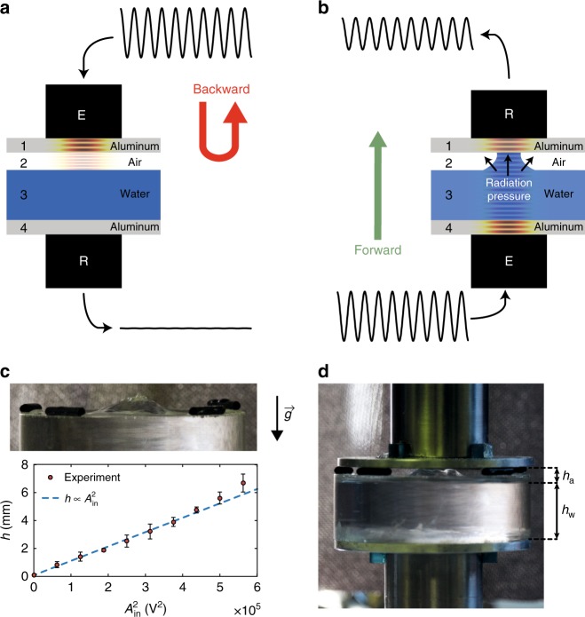
Schematic principle of the concept and a picture of the prototype. a, b Schematic diagrams of the forward (emitter E at the bottom, receiver R at the top) and backward (emitter E at the top, receiver R at the bottom) transmission configurations, respectively. c Radiation pressure effect on the water surface quasi-static deformation. Picture of the water bump, and experimental height as a function of the input electrical amplitude squared (error bars correspond to the standard deviation of 50 data points collected over 10 s for each amplitude); d picture of the tested device when forward transmission is active

