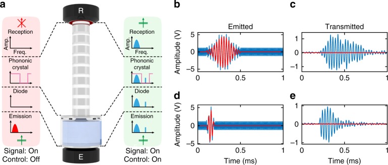
Fig. 4.
Experimental demonstration of the underlying switch principle: a diagrams of the switch prototype; a phononic crystal (PC) has been added on top of the acoustic diode. The switch working principle is schematically described by the effect of activating a control wave on the transmitted signal wave. b, d emitted electrical waveforms (before a +60 dB amplification by the power amplifier) for a harmonic control signal of frequency kHz and a signal wave in the form of a Gaussian pulse with a carrier frequency f0 = 35 kHz and a spectral full width at half maximum of 5 kHz (b) and 20 kHz (d). c, e output signals transmitted by the switch device. The continuous red lines represent waveforms where the control signal is not turned on, while the continuous blue lines represent signals with the control signal on

