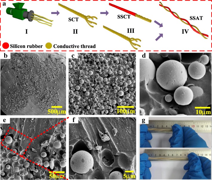
Fig. 1.
a Schematic diagram for fabricating process of the SATT device. b–d The SEM image of the SSCT cross-section view at different magnifications. e, f The SEM image of the connection position between SCT and coated silicone rubber at different magnifications. g Photographs of the prepared SATT with demonstrations of being stretched at ≈ 100% strain.

