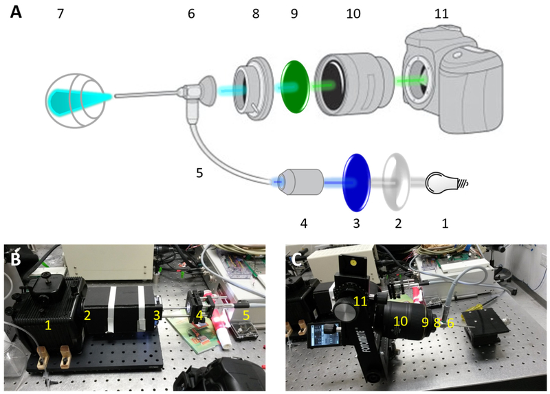
Figure 1:
(A) System schematic diagram. 1: light source, 2: convex lens, 3: excitation filter, 4: objective lens, 5: optic fiber, 6: endoscope, 7: in vivo eye, 8: adaptor, 9: emission filter, 10: lens of camera, 11: camera. (B) Excitation part of the system, including compartments 1 through 5 in (A). (C) Emission part of the system, including compartments 6 through 11 in (A).

