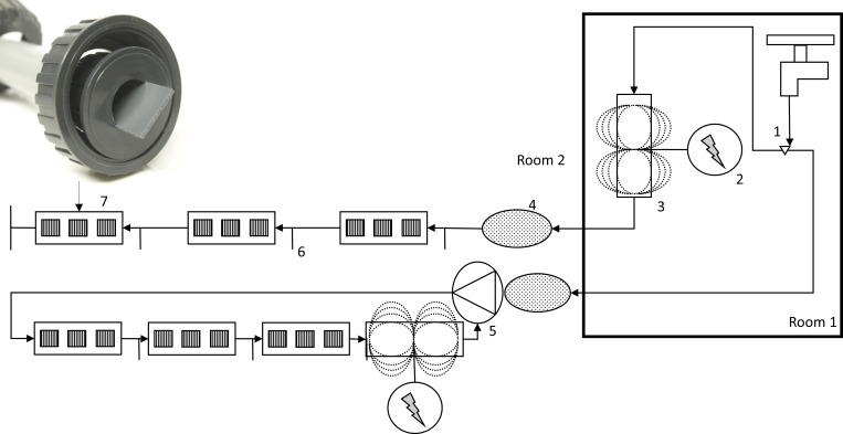
Fig 1. Schematic representation of models of drinking systems.
Water supply (1); control unit (2); treatment unit (3); pressure regulator (4); peristaltic pump (5); sampling nipple (6); replaceable PVC-pipes with PVC-coupons (7). Picture shows position of coupons in replaceable pipes. Bold frame indicates a separate room. Untreated systems (controls without the electromagnetic device) are not shown.

