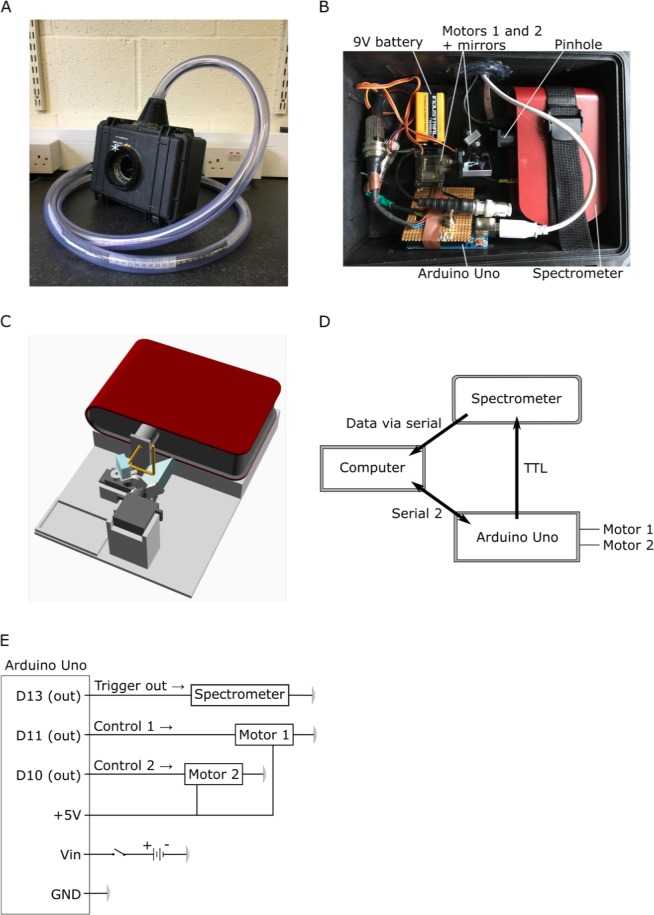
Figure 1.
A Hyperspectral scanner for low-cost natural imaging. (A) The waterproof casing with a window (white asterisk) for light to enter. The PVC tube on top protects the cables connected to the computer. (B) Internal arrangement of parts: the spectrometer, Arduino Uno microcontroller, 9 V battery, two servo motors (Motors 1 and 2) with mirrors attached to them and a round pinhole (r = 0.5 mm). (C) A schematic illustration of the optical path (Arduino, 9 V battery and chords are left out for clarity). First, light beam (yellow lines) enters the system from above through the window. Light reaches first the larger mirror underneath the window of the casing, reflects to the smaller mirror and from there through the pinhole to the spectrometer’s slit. The pinhole is placed at 23 mm distance from the slit (20 µm × 1.2 mm effective slit dimension). Light deflected off the first mirror is partly shadowed by the edges of the casing, which creates dark stripes at the horizontal edges of the scanned images when the box is closed. These edges are cropped in the presented example scans (Figs 3, 8). Spectral filtering by the quartz window was corrected for in postprocessing (Fig. 3D,E). (D) Operational logic. The scanning path is uploaded to the Arduino from the computer via Serial 2 connection to define the motor movements. After each movement the spectrophotometer is triggered via TTL to take a measurement and send the data to the computer vial serial. The ongoing state of the scanning path is fed from the control circuit to the computer. (E) Circuit diagram.

