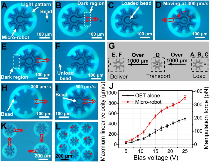
Fig. 2.
Microrobot operations. Bright-field microscope images (from Movie S3) of a cogwheel-shaped microrobot and a 15-μm-diameter polystyrene bead, with (A) a fully enclosed microrobot being aligned with the bead, (B) a partially enclosed microrobot in ‘load’ mode, (C) a partially enclosed microrobot with bead immediately after loading, (D) a fully enclosed microrobot and bead in “translate” mode, (E) a partially enclosed microrobot midway through the process of “delivery,” and (F) a partially enclosed microrobot after bead delivery. (G) Schematic illustrating the spatial relationship between A–C (load), D (transport), and E and F (delivery). Bright-field microscope images depicting the manipulation of a 15-μm-diameter polystyrene bead (H) by OET alone at 300 μm/s and (I) with the microrobot at 500 μm/s. (J) Maximum linear velocity (left axis) and corresponding DEP manipulation force (right axis) as a function of bias voltage for a bead translated alone (black) or inside a microrobot (red). Error bars represent ±1 SD from 5 measurements for each condition. Bright-field microscopy images (from Movie S4) demonstrating (K) the translation of 4 microrobots bearing payloads (one or two 15-μm-diameter polystyrene beads) in different directions, and (L) the rotation of 8 microrobots with each robot rotating at a different angular velocity. In images, open red arrows represent translation and dashed red arrows represent rotation.

