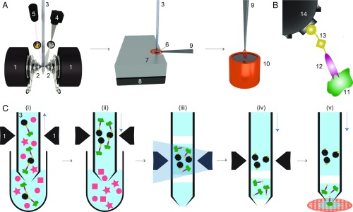
Fig. 1.
Schematic workflow for microfluidic protein isolation and cryo-EM grid preparation. (A) Hardware for protein isolation and cryo-EM grid preparation. The electromagnetic trap consists of 2 electromagnets (1) that produce a strong magnetic field gradient via their water-cooled iron tips (2). Sample processing in the capillary (3) is monitored by a camera (4), and a UV LED (5) allows photo-cleavage (B) of the sample, both via mirrors. After protein isolation, the capillary nozzle is moved above a cryo-EM grid covered with a holey carbon film (6). The cryo-EM grid is positioned on a stage (7) that is temperature controlled by a Peltier element (8) and held with a Peltier-cooled tweezer (9). The isolated protein is directly written onto the grid and plunge-frozen in liquid ethane (10). (B) Composite material for “protein fishing.” The target protein (11) is recognized by a Fab (12) that is covalently modified by a photo-cleavable cross-linker (13). The linker molecule ends with a biotin moiety, which strongly binds to the streptavidin-coated bead (14). (C) Protein isolation workflow. (i) Magnetic beads are incubated with biotinylated Fabs and cell lysate to capture the target structures (green). Less than 900 nL of sample is aspirated into the microcapillary for the protein isolation. (ii) The magnetic beads are immobilized in the magnetic trap (1). Nonbound lysate components (red) are flushed out. (iii) Illumination with UV light breaks the cross-linker. Before photoelution, 2 air bubbles are introduced and serve as boundaries to avoid dilution of the released proteins by diffusion (see SI Appendix, Figs. S1 and S3 for details). (iv) Separation of the capturing magnetic beads and the eluted proteins. (v) The isolated target proteins are directly deposited on a cryo-EM grid for vitrification. The blue vertical arrows indicate the pump direction.

