Figure 5.
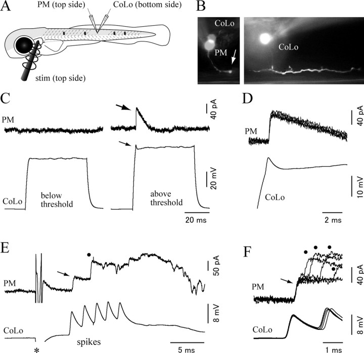
Paired recording between the CoLo neuron and the primary motoneuron. A, A schematic illustrates the paired recording shown in B–F. The recording was made using a 3 dpf larva. A stimulation electrode was placed near the ear on the top side. One patch electrode was placed targeting the primary motoneuron (PM) on the top side, whereas the other patch electrode was placed targeting the CoLo neuron on the bottom side. The black dots represent tungsten holding pins. B, The pictures show images of the recorded cells. Montages were made to show the morphology of each cell. The left shows the morphology of a primary motoneuron. The arrow shows its torn axon at the edge of the spinal cord. The image of a CoLo soma located on the opposite side of the spinal cord is superimposed for the comparison of relative locations of the two cells. The right shows the morphology of the CoLo neuron. C, In this experiment, and the experiments shown in D–F, the CoLo neuron was recorded in a current-clamp mode, whereas the primary motoneuron was recorded in a voltage-clamp mode with the holding potential at −50 mV. The chloride reversal potential calculated with the experimental condition is −70 mV. The left shows that there was no response in the primary motoneuron when the depolarizing pulse in the CoLo was below threshold, whereas the right shows that, during a current pulse above the threshold, an evoked CoLo spike (thin arrow) leads to an IPSC in the primary motoneuron (thick arrow). D, Five superimposed traces of IPSCs in the primary motoneuron. The traces show short, constant latency IPSCs. Only one spike in the CoLo neuron is shown for simplicity. E, Responses of the CoLo neuron and the primary motoneuron during an escape trial. An electrical stimulation was applied at the time point marked by the asterisk. With a short latency from the stimulus, the CoLo neuron expressed several successive spikes (labeled as “spikes”). These spikes likely correspond to the activity associated with an escape (Fig. 6). The primary motoneuron received IPSCs during the escape. The timing of the earliest IPSC (arrow) coincides with the first CoLo spike. The timing of the second IPSC (dot) does not coincide with any of the CoLo spikes. F, Five superimposed traces of IPSCs in the primary motoneuron and spikes in the CoLo neuron. In all traces, the timings of the earliest IPSCs (arrow) perfectly coincide with those of the first CoLo spikes. Subsequently, the primary motoneuron received IPSCs at various timings (dots) that are not related to CoLo spikes.

