Figure 3.
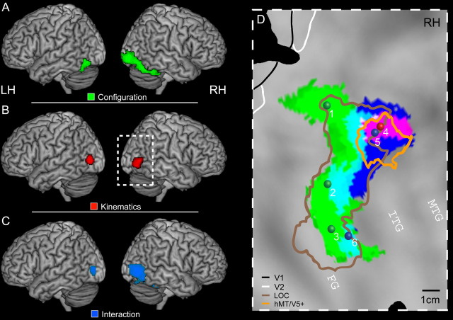
Results of experiment 1. A–C show the t score maps for the main effect of configuration (green), the main effect of kinematics (red), and the interaction (blue) thresholded at p < 0.001, uncorrected, projected onto a rendered brain. D, Activations of the main effects and the interaction projected onto the posterior part of the flattened right hemisphere of the PALS atlas. The symbols indicate the position of the local maxima obtained in the different contrasts (Table 1). The colored outlines indicate the location (group analysis) of the hMT/V5+ (orange) and the LOC (brown). LH, Left hemisphere; RH, right hemisphere.

