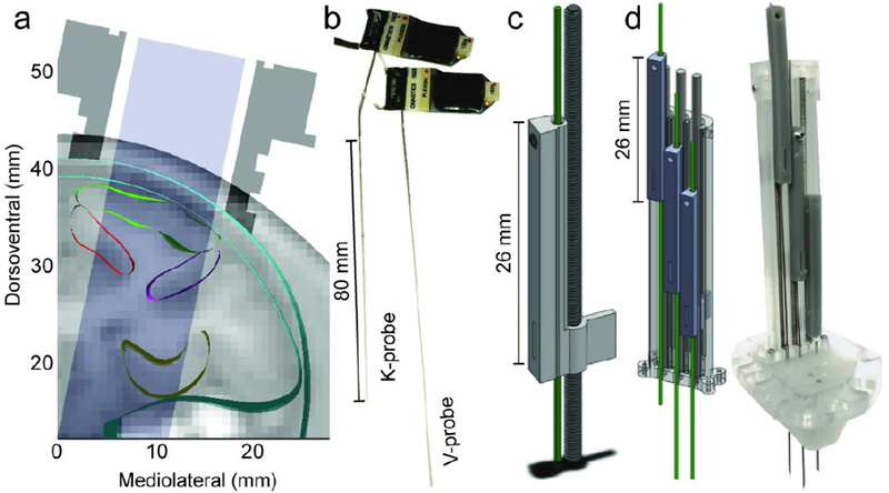
Figure 1.

a) Cross-section of anatomical model with MRI slice (subj. C, coronal section 24 mm anterior to the interaural line) with cortical regions outlined. Chamber profile in dark grey; accessible area in light grey. b) Multisite linear probes (left: K-probe, right: V-probe) with headstages and groundwires attached. K-probes have a 20° bend 8 mm above electrode shank, c) Rendering of single shuttle and drive screw. Green shows track for electrode. Scale bar = 26 mm. d) Render (left) and photo (right) of 3 drives assembled into a linear tower and placed on a planar grid (clear). Hypodermic needles serve as guide tubes. Scale bar = 26 mm.
