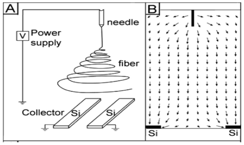
Figure 14.
Schematic diagram showing electrospinning setup for forming uniaxially aligned nanofibers. (A) A collector with two pieces of conductive silicon stripes separated by a gap. (B) Electric field strength around the needle and the collector. The arrows denote the direction of the electrostatic field lines. Reproduced with permission from [135], published by American Chemical Society, 2003.

