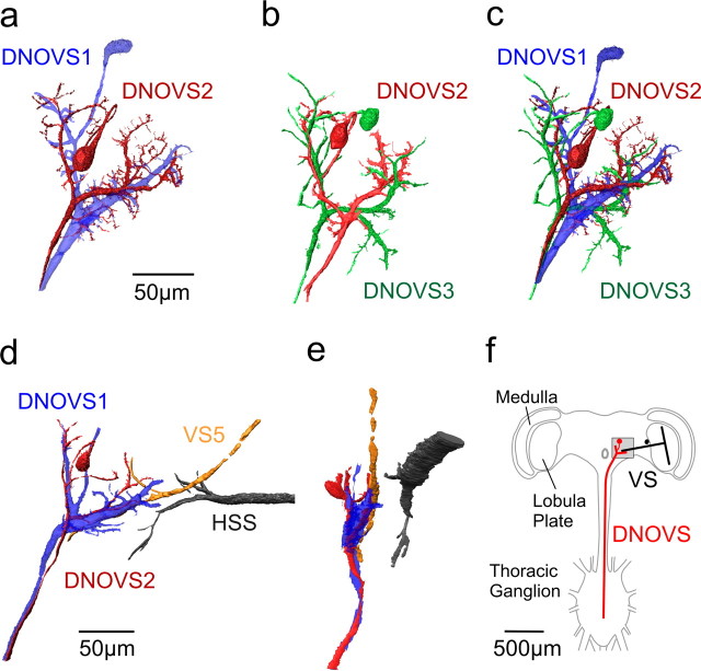
Figure 1.
Anatomy of DNOVS cells. a, Two-photon imaging of DNOVS1 and DNOVS2. DNOVS1 (blue) was filled with Alexa 568, and DNOVS2 (red) was filled with Alexa 488. b, Two-photon imaging of DNOVS2 and DNOVS3. DNOVS2 (red) was filled with Alexa 568, and DNOVS3 (green) was filled with Alexa 488. c, Reconstruction of all three DNOVS cells. The reconstructions in a and b were superimposed according to the position of DNOVS2. In contrast to DNOVS1, DNOVS2 and DNOVS3 bifurcate in their lateral dendritic branch with numerous short processes. d, x–y projection of DNOVS1 (blue), DNOVS2 (red), VS5 (yellow), and HSS (black). e, Same as in d, but in a y–z projection. The side view shows that the terminal of VS5 and the dendrites of the DNOVS cells are in close vicinity, whereas the terminal of the HSS cell lies in different depth. Cells within two-photon image stacks were reconstructed with the AMIRA software package (see Material and Methods). F, Schematic drawing of the fly nervous system showing VS cells within the lobula plate of the fly brain and the DNOVS cells postsynaptically projecting from the brain in the thoracic ganglion. Image stacks from a–e were taken in the highlighted region.

