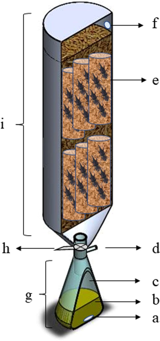
Figure 7.

Scheme of the experimental apparatus of the diaphragm cell: (a) magnetic stirring bar, (b) liquid phase (eugenol or clove essential oil), (c) headspace of the Büchner flask with the volatile phase, (d) lateral opening of the Büchner flask sealed with a rubber septum for sampling of the volatile phase, (e) cages with grain and insects used for the bioassays, (f) rubber septum for sampling of the volatile phase after passing through the column of grain, (g) the bottom chamber of the prototype, (h) ball valve connecting the parts of the system, and (i) upper chamber of the prototype.
