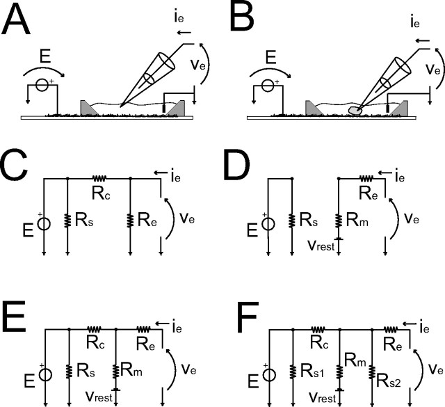
Figure 3.
Modeling electrical stimulation delivered via the SWNT layer. A, B, Sketch of the bath (A) or of the whole-cell pipette configurations (B). The DC equivalent circuit of A is represented in C. For B, the hypothesis on the resistive–capacitive nature of the SWNT–cell coupling, as well as the quality of the whole-cell configuration, must become explicit. These are ideal whole-cell patch clamp with (E) or without (D) a resistive electrical coupling between the cytoplasm and SWNT. Finally, F equivalently captures both of the previous situations (D–F), under the hypothesis of a nonideal whole-cell configuration. The value of Rc in one case has the same meaning as in C but in the other, has the same meaning as in E.

