
Figure 3.
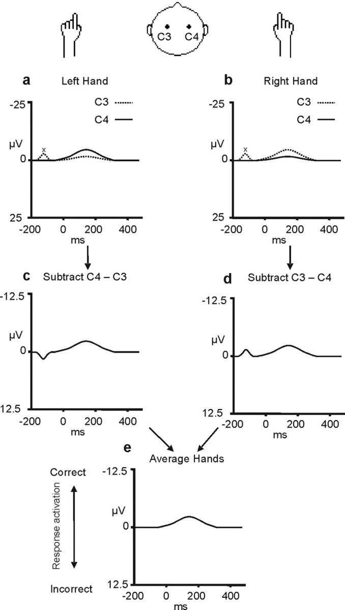
Derivation of the LRP. The top row of figures (a, b) show the event-related potentials recorded at the C3 and C4 electrodes over the left and right motor cortex (dotted and continuous lines, respectively) when left-hand (a) and right-hand (b) responses are made. As can be seen, there is a signal in the event-related potential recorded from each hemisphere and it is more negative (upward direction) over the motor cortex contralateral to the hand that moves. In the next stage (c, d), a difference wave is derived that reflects the difference in the signal recorded from the C3 and C4 electrodes (C4 − C3 for the left-hand movements in c; C3 − C4 for the right-hand movements in d). These two difference waves are then averaged to form the LRP (e). The LRP derivation removes any activity unrelated to the process of movement preparation that is not lateralized with respect to the moving hand (for example, the deviation in the signal labeled “x”). This figure was adapted from Coles (1989). A negative LRP (deflection in the upward direction) indicates greater activation of the correct as opposed to the incorrect response representation.