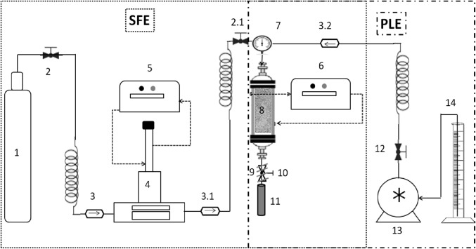
Fig. 1.
Scheme of the SFE and PLE system. CO2 cylinder [1]; Needle type Valve [2, 2.1 and 12]; Anti reflux valve [3, 3.1 and 3.2]; High pressure syringe pump [4]; Ultra thermostatic recirculation bath [5 and 6]; Pressure gauge [7]; Extraction column [8]; Micrometric valve [9]; Heating tape [10]; Glass bottles collector [11]; HPLC pump [13]; Solvent cylinder [14]

