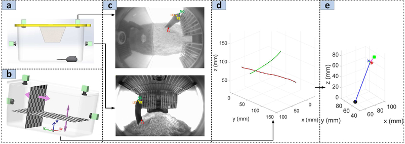
Fig. 2.
(a) 3D CAD illustrating the video acquisition unit augmented with overhead cameras enabling synchronized stereo acquisition. (b) Cartesian coordinate definition for cage with origin at the center of the cage floor. Each checkerboard pattern grid is moved at known increments to generate the image-to-physical coordinates lookup tables. (c) Example manual annotation of the key-points from top and side camera. (d) Reconstruction of the nose 3D position using the lookup tables . The red line is due to the nose annotation in the side camera image while the green line is due to the top camera annotation. The black dots in each line show the actual 3D points comprising the set {γ} corresponding to each annotated image position. (e) The 3D reconstructed ground-truth pose

