
Figure 3.
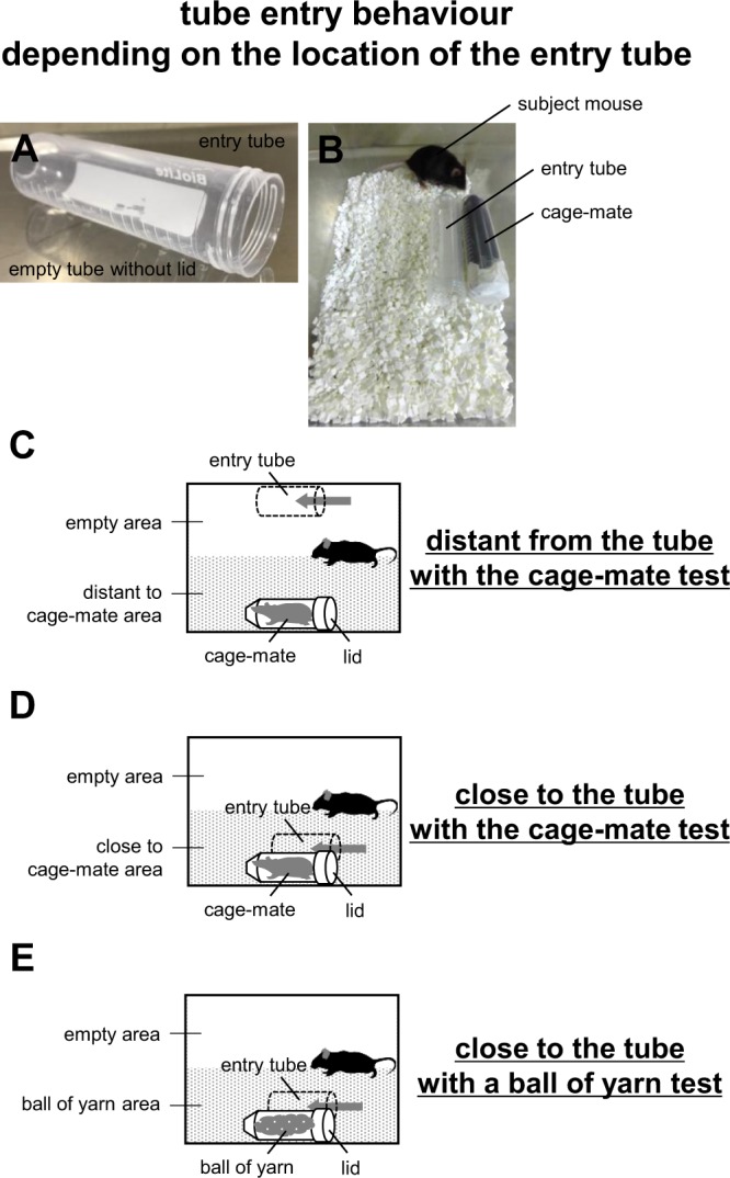
Schematic diagram of tube entry tests depending on the location of the tube. (A) A sample image of the entry tube. (B) A sample picture of the setup with the entry tube close to the tube containing the cage-mate in the new home cage. (C) Schematic diagram of the setup with the entry tube distant from the tube containing the cage-mate. (D) Schematic diagram of the setup with the entry tube close to the tube with the cage-mate. (E) Schematic diagram of the setup showing the entry tube close to the tube with a ball of yarn.