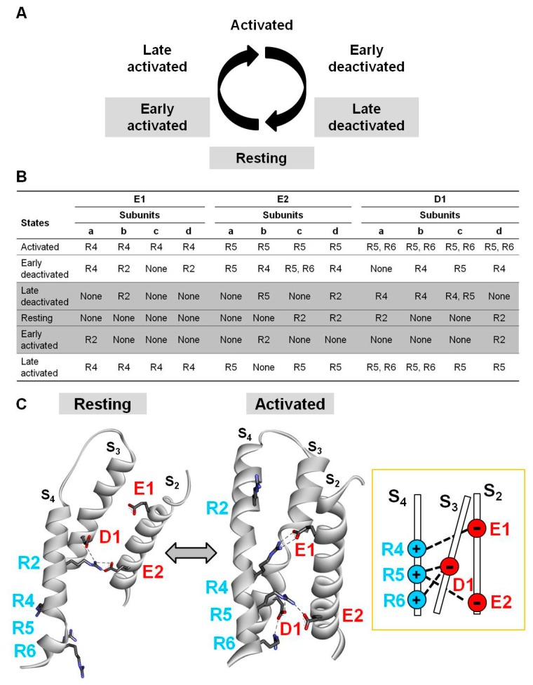
Figure 4.
Multistate modelling of Kv7.2 voltage-sensing domain (VSD). (A) Schematic representation of six gating states of the VSD. (B) Electrostatic interactions identified between E130 (E1), E140 (E2), or D172 (D1) and R201 (R2), R207 (R4), R210 (R5), or R213 (R6) in each gating state for each Kv7.2 subunit (a, b, c, and d). shaded rows correspond to the resting and nearby resting states also highlighted in grey in panel A. (C) Homology models of a single Kv7.2 d subunit in resting or activated VSD states. Electrostatic interactions of E1, E2, and D1 residues have been highlighted with dotted lines. The inset on the right indicates a schematic drawing of the VSD interactions occurring in the activated state.

