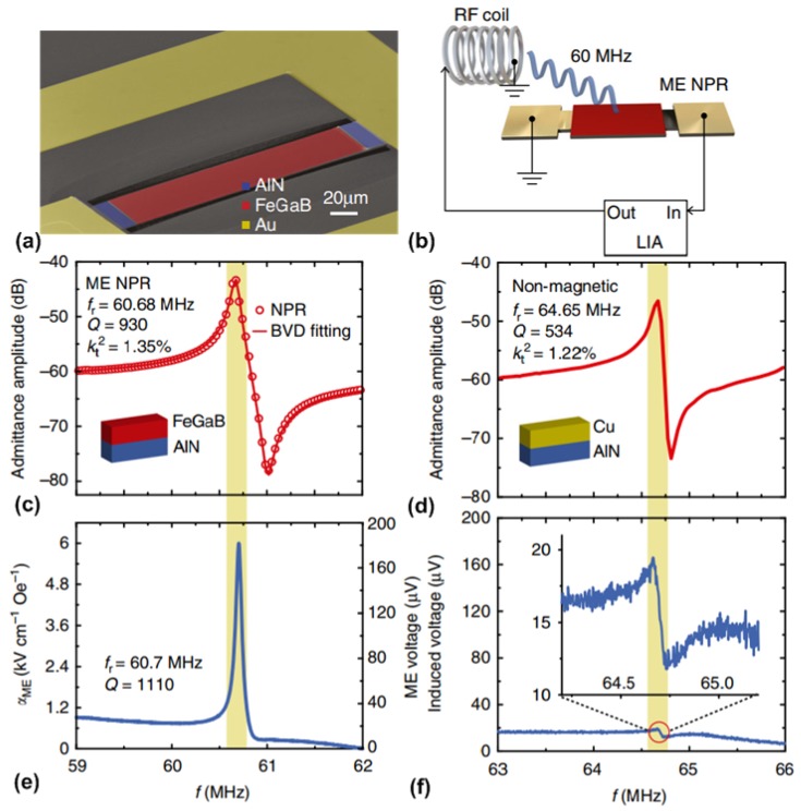
Figure 9.
(a) SEM of the NPR-type mechanical antenna; (b) schematic of the measurement setup using RF coil and high-frequency lock-in amplifier; (c) measured admittance frequency spectrum of the NPR-type mechanical antenna; (d) measured admittance frequency spectrum of the nonmagnetic Cu/AlN control device; (e) ME coupling coefficient (left axis) and the induced ME voltage (right axis) versus the excitation frequency of RF-coil for NPR-type mechanical antenna; and (f) measured induced voltage versus the excitation frequency of RF-coil for Cu/AlN control device. The inset illustrates the zoomed-in view of the resonance peak area (red circle). This figure is reproduced from [121].

