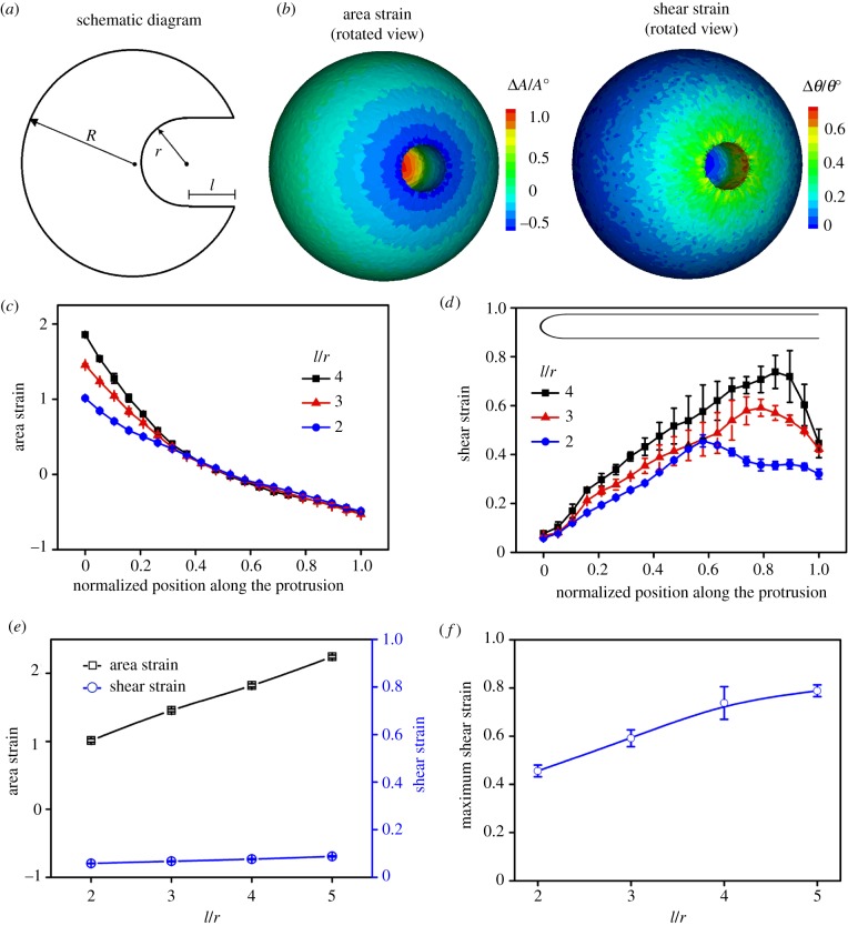
Figure 3.
The distributions of the area and shear strains along the protrusions depend on the radius r and length l. (a) A schematic diagram of an inward protrusion with representative geometric parameters r and l in an FC. (b) The surface distribution of the area and shear strains for an FC with an inward protrusion of r = 500 nm and l = 2 µm. (c) The area strain decreases from the tip to the base along the protrusions for different l/r. (d) The shear strain peaks close to the base of the protrusions for different l/r. (e) The maximum area strain occurs at the tip of the protrusions and grows monotonically with l/r, whereas the shear strain at the tip only varies slightly at the tip. (f) The maximum shear strain at the base of the protrusions grows monotonically with l/r. For all cases, the protrusion radius r is 500 nm. (Online version in colour.)

