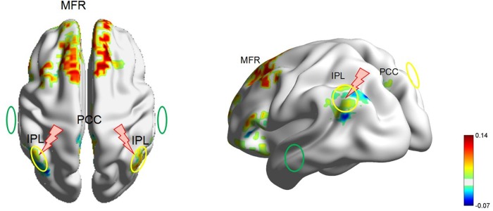
FIGURE 3.
The locations of the rTMS and tDCS targets in a head model of patient 1. The yellow circle denotes the anode electrode over P3 or P4. The green circle denotes the cathode electrode over T3 or T4. The red lightning mark denotes the rTMS site over P3 or P4. For the 20-min treatment on the right hemisphere, the anodal tDCS was delivered over P4, and the cathodal tDCS was delivered over T3. Meanwhile, 5-Hz rTMS was delivered precisely over the anodal electrode at P4. Then, for the next 20-min treatment on the left hemisphere, the anodal tDCS was delivered over P3, and the cathodal tDCS was delivered over T4. Meanwhile, 5-Hz rTMS was delivered precisely over the anodal electrode at P3. rTMS, repetitive transcranial magnetic stimulation; tDCS, transcranial direct current stimulation; fMRI, functional magnetic resonance imaging; IPL, inferior parietal lobe; PCC, posterior cingulate cortex; MFR, mesiofrontal region.

