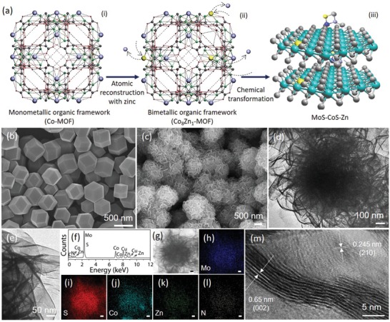
Figure 1.

Schematic summary of the synthesis procedure and morphology analysis. a) Successive transformation of (iii) zinc–nitrogen coordinated cobalt–molybdenum disulfide from (i) monometallic organic framework (Co‐MOF). Arrows represent the key processes involved. a)‐(ii) shows the crystal structure of bimetallic organic framework (Co8Zn1‐MOF). In the MOFs ((i) and (ii)), purple, yellow, green, dark grey, and red represent Co, Zn, N, C, and H, respectively. In the MoS–CoS–Zn crystal structure ((iii)), green, grey, yellow, dark blue, and purple represent Mo, S, Zn, N, and Co atoms, respectively. b) SEM image of the bimetallic organic framework (Co8Zn1‐MOF), which is structurally presented in (a)‐(ii). c) SEM and d,e) TEM images, and f) TEM‐EDX spectrum of MoS–CoS–Zn. g) STEM image and corresponding elemental mapping images showing the distribution of h) Mo, i) S, j) Co, k) Zn, and l) N in MoS–CoS–Zn. The scale bar shows 100 nm. m) HRTEM image of the MoS–CoS–Zn.
