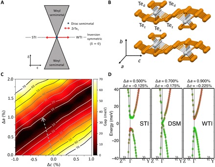
Fig. 1. Topological phase diagram and band structures of ZrTe5.

(A) Universal phase diagram of topological insulators proposed by Murakami for a 3D system (2, 3, 10). The control parameter 𝛿 describes the breaking of inversion symmetry. The control parameter ϵ does not break inversion symmetry. (B) Crystal structure of ZrTe5. Chains of ZrTe3 prisms (consisting of Tea and Ted atoms) extend along the a axis. These chains are connected by Tez atoms along the c axis to form layers. These layers are vdW bonded in the b axis direction. (C) Size of bandgap Eg at the Γ point as functions of strains in the a and c lattice directions. The dashed gray arrow indicates the anisotropic strain induced by a uniaxial stress along the a axis direction, as governed by the calculated Poisson’s ratio ϵaa = −4.0ϵcc. (D) Band structures for different strain states taken at points along the Poisson’s ratio path. These points (from left to right) correspond to STI, Dirac semimetal, and WTI, respectively. Fermi level is defined as the zero energy, and the k-point labeling is based on the primitive unit cell. A band inversion involving Ted and Tez p orbitals (shown as red and green colors, respectively) is seen in the STI phase.
