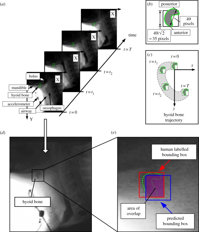
Figure 3.
The hyoid bone movement for model training was determined from human raters of VFSS images and was measured as a two-dimensional time sequence corresponding to the x and y spatial axes, as shown in (c). The bounding box represented the hyoid bone as shown in (b). The hyoid bone’s demarcation line in green was approximated for reader’s visualization. However, owing to reduced image quality, the demarcation of the hyoid bone was often unclear, as shown in (d). The coordinates of the anterior and posterior points were used to locate the hyoid bone, as shown in (b). The anterior point of the hyoid bone was tracked in this study, because the posterior point was not always visible. In (a), when t = 0, t1 and t2, the posterior point was totally shaded. (e) The bounding boxes helped confirm the effective area of the hyoid bone and the overlapped area between the bounding boxes gives the accuracy in hyoid bone tracking.

