Figure 2.

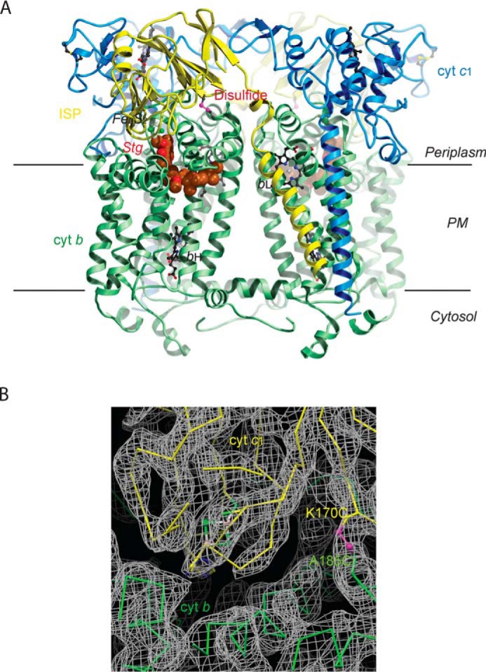
Structure of Rsbc1/stg with the ISP–ED in the b-site. A, overall structure of the dimeric Rsbc1 with the ISP–ED trapped in the b-site. The cyt b subunits are shown in green, cyt c1 in blue, and the ISP in yellow. Stigmatellin is rendered as a CPK model with carbon atoms colored brown. The engineered disulfide bridge (ISP) Cys-70–Cys-185 (cyt b) is shown in magenta. Heme groups are depicted as ball-and-stick models with carbon atoms in black, nitrogen in blue, and oxygen in red. The Fe2S2 cluster of ISP is shown as balls with iron atoms in orange and sulfur in green. B, electron density in the vicinity of the disulfide bridge (magenta) between ISP (shown in yellow) and cyt b (shown in green). The continuous density around this bridge (K170C of ISP and A185C of cyt b) shows that it formed correctly to arrest ISP–ED in the b-state.
