
Figure 9.
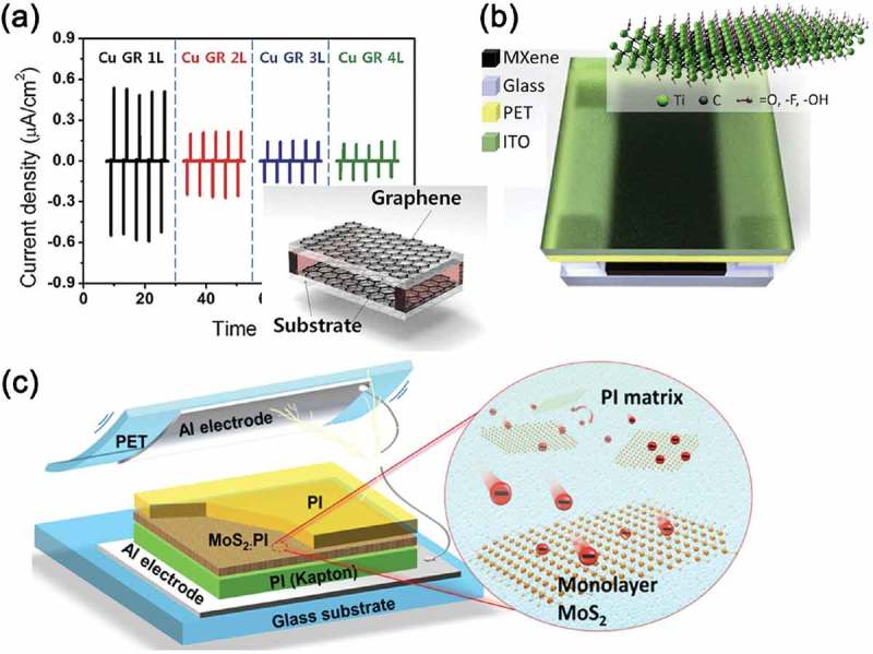
(a) Output current density generated by the Cu foil-grown 1L-, 2L-, 3L-, and 4L-stacked graphene-based TEG under same compressive force. Inset: a schematic illustration of graphene-based transparent TEG device with a spacer structure. Reprinted with permission from [123]. Copyright 2014 John Wiley & Sons. (b) Schematics of MXene TEG (MXene/glass for the bottom electrode) with an air gap between top and bottom electrodes. ITO stands for indium tin oxide and PET for polyethylene terephthalate. Inset: illustration of Ti3C2Tx MXene structure. Reprinted with permission from [124]. Copyright 2018 Elsevier. (c) Device structure of the TEG made by the MoS2 monolayer films (left). Schematics of the electron transfer from the PI matrix to the MoS2 monolayers (right). Reprinted with permission from [125]. Copyright 2017 American Chemical Society.