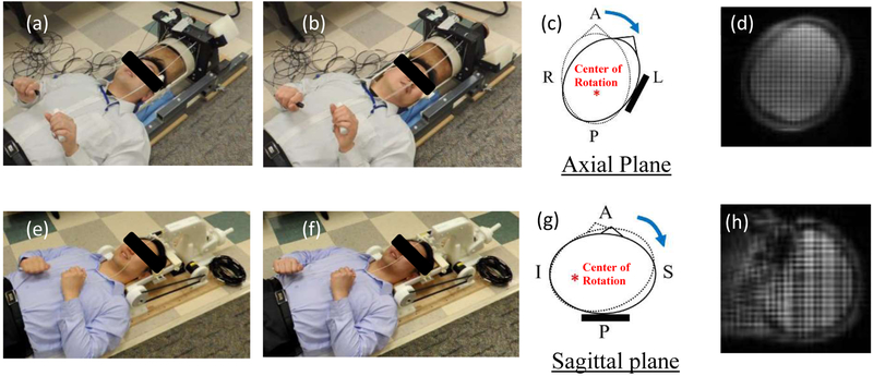
Figure 1.
a) The head rotation device (rest position): b) The head rotation device (stop position): c) Schematic of head at rest (dotted line) and stop (solid line) positions for head rotation test: d) A tagged image of head rotation test: e) The head extension device (rest position): f) The head extension device (stop position): g) Schematic of head at rest (dotted line) and stop (solid line) positions for head extension test: h) A tagged image of head extension test. A: Anterior: P: Posterior: R: Right: L: Left: S: Superior: I: Infereior.

