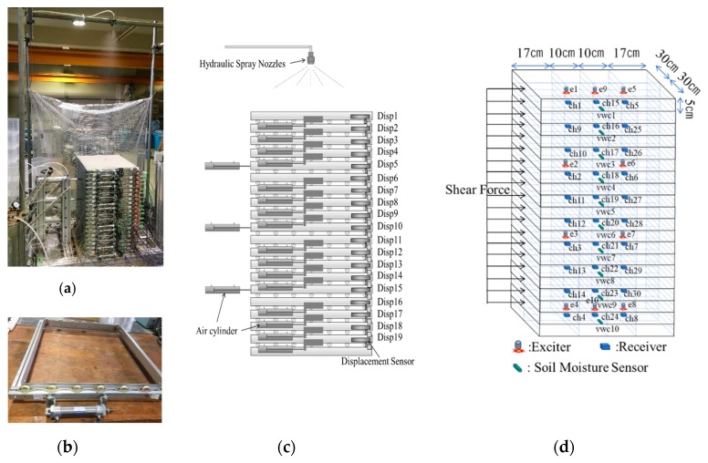
Figure 3.
Multi-layer shear model and sensors layout. (a) A photo overview of the multi-layer shear model; (b) an independent frame of the multi-layer shear model; (c) the layout of air cylinders and displacement meters, Dis1~Dis19 are the displacement meters; (d) the layout of sensors in the soil. E1~E10 are the exciters; CH01~CH30 are the receivers; VWC1~VWC10 are the soil moisture sensors.

