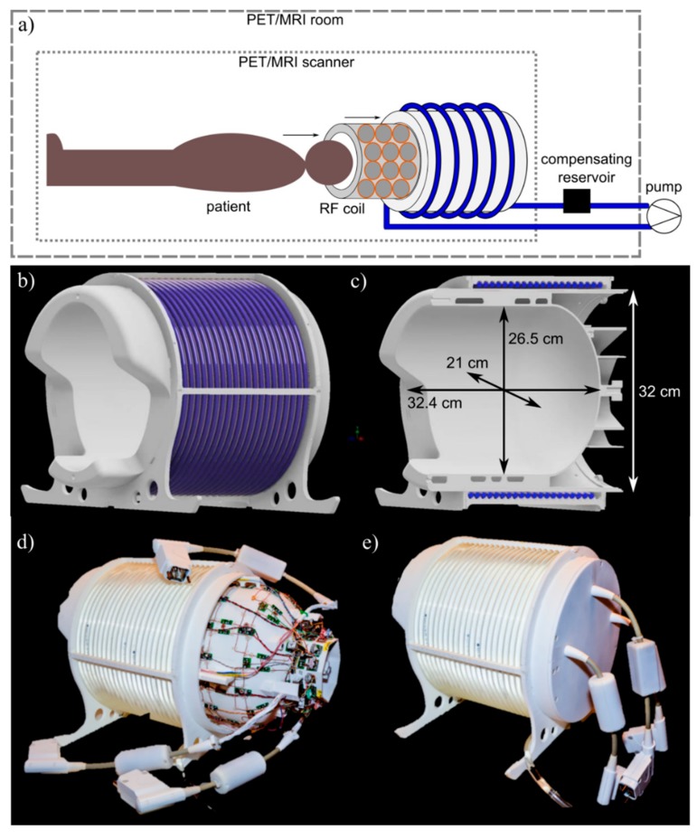
Figure 1.
System overview. (a) Sketch of the complete setup consisting of transmission source (TxS) system and integrated radiofrequency (RF) receiver array, and its positioning relative to the PET/MR scanner. (b,c) 3D CAD drawing of the mechanical support with mounted polyurethane hose. The coil housing is shown in white, and the hose in blue. (d) Photograph of the complete RF coil integrated with the TxS system, with RF coil slid slightly out of the surrounding TxS system, and (e) in final, mounted configuration.

